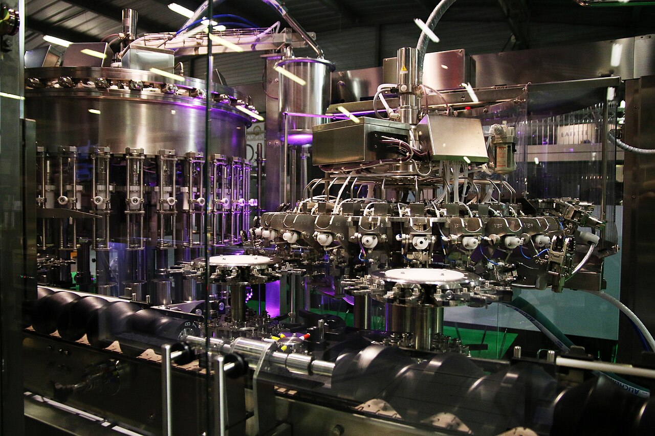
Lab · Electrical control of industrial mechanisms
The programmable controller
From wiring to program, on the PLC-200 trainer
[Instructor] · [Group] · 2026–2027
Today
The route through the session
1
The PLC
2
The PLC-200 trainer
3
History and definitions
4
GRAFCET
5
Ladder
6
GRAFCET or ladder?
7
Inputs, outputs, actions
8
The lab and the report
1 · The PLC
Senses, a brain, muscles
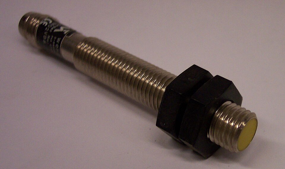
INPUTS
Sensors, push buttons, switches
I0.0 … I1.5
PROGRAM
The CPU reads, computes, decides
over and over
OUTPUTS
Motors, lamps, relays
Q0.0 … Q1.1
1 · The PLC
Every size, one principle
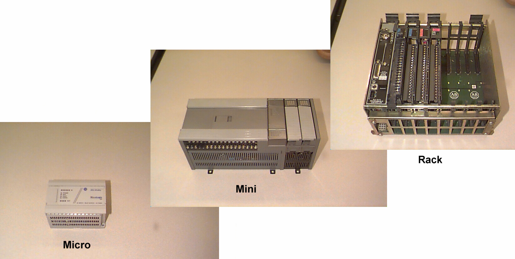
You find them in:
packaging
lifts
pumping
conveyors
traffic lights
hoisting
2 · The PLC-200 trainer
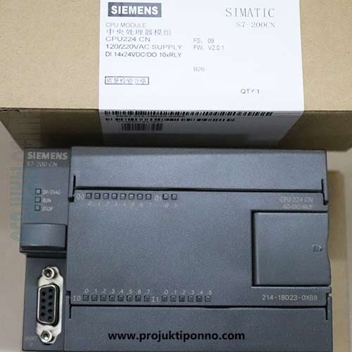
The heart of the trainer: Siemens S7-200, CPU 224
14
digital inputs
I0.0 – I1.5
10
outputs
Q0.0 – Q1.1
2
potentiometers
SMB28, SMB29
2
pulse outputs
Q0.0, Q0.1
6
high-speed counters
HSC0 – HSC5
1
PPI port
USB/PPI cable
2 · The PLC-200 trainer
Everything connects to the CPU
PC · STEP 7-Micro/WIN
CPU 224
S7-200
I · Q · M · V · T · C
2 potentiometers
Push buttons · switches
Proximity · micro-switch
A/B encoder
Lamps · relays · display
DC motor
Stepper motor
USB/PPI cable
INPUTS
OUTPUTS
2 · The PLC-200 trainer
Programming in 5 moves
1
Write
the ladder network
2
Compile
zero errors
3
Download
CPU in STOP
4
RUN
the program runs
5
Monitor
program status
The software: STEP 7-Micro/WIN. Once downloaded, the PLC no longer needs the PC.
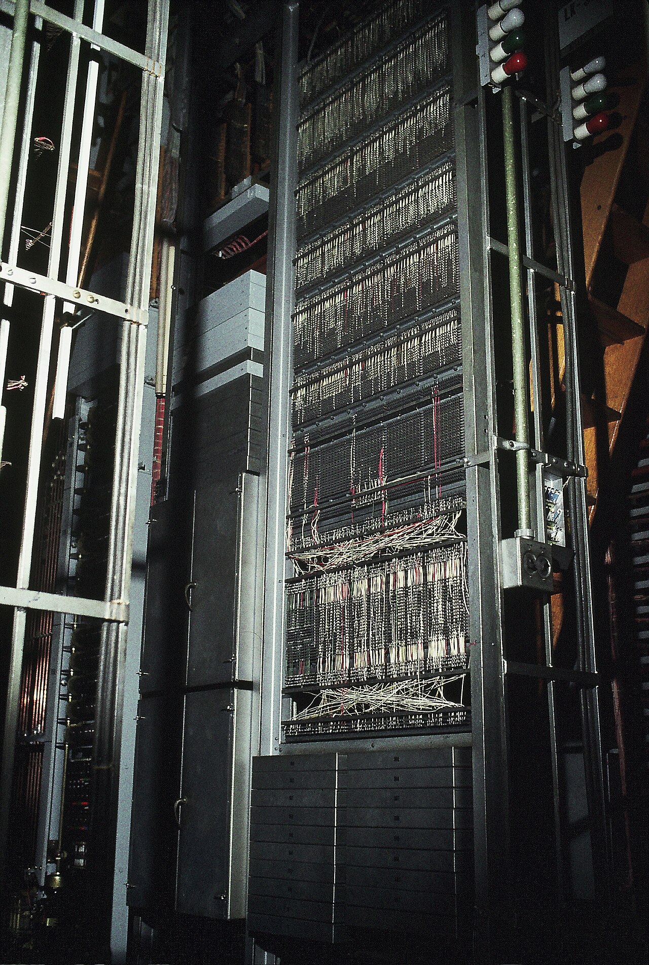
3 · History
Before 1968: walls of relays
The logic is the wiring
Changing the logic means rewiring, days of downtime
Finding a fault: wire by wire
3 · History
From relay cabinet to PLC
1968
1969
1977
1979
1993
2009
General Motors wants to replace its relays
Modicon 084: the first PLC
GRAFCET is born in France
Siemens SIMATIC S5
IEC 61131-3 standard: the languages
SIMATIC S7-1200, successor of the S7-200
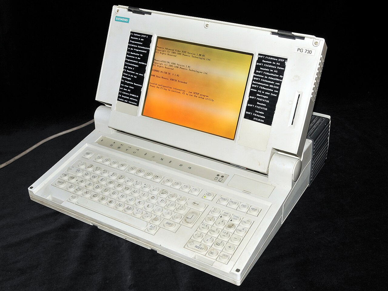
Orange: the machines. Blue: languages and standards.
Our S7-200: the 1990s–2000s generation.
3 · History
Wired relays or a PLC?
| To… | Relay cabinet | PLC |
|---|---|---|
| change the logic | rewire | reprogram |
| time, count | one relay per function | one instruction |
| find a fault | multimeter, drawings | program status, LEDs |
| space | a cabinet | a small box |
The logic leaves the wires and moves into a program.
3 · Definitions
Six words to remember
PLC
Programmable logic controller: a hardened computer that controls a machine.
Input
A signal coming into the PLC: sensor, push button.
Output
A signal sent by the PLC: motor, lamp, relay.
Program
The logic you write and the CPU executes.
Scan
Read, compute, write, then start again: a few milliseconds.
Digital
On/off: 0 or 1, open or closed.
3 · Definitions
The scan cycle: read, compute, write
1 · Read the inputs
2 · Run the program
3 · Write the outputs
a few ms
over and over
A pulse shorter than one scan can be missed: it goes to a high-speed counter.
An output written in two networks: the last one wins.
3 · Definitions
Reading an address
I0.3
I = input
byte no. 0
bit no. 3 (0 to 7)
= the 4th input of byte 0 (counting starts at 0)
I
inputs
Q
outputs
M
memory bits
V
variables
T
timers
C
counters
SM
system bits
4 · GRAFCET
Steps, transitions, actions
0
1
2
PUMP
READY LAMP
COIN · BUTTON
t/X1/5 s
cup removed
Initial step: active at start-up
Transition: we move on when the condition is true
Action: what the machine does
Timer: 5 s after step 1 becomes active
Example: a drinks dispenser
4 · GRAFCET
How a GRAFCET moves forward
Previous step active AND condition true: the transition fires, the next step turns on, the previous one turns off.
BEFORE
1
2
b = 1
← active
transition fires
AFTER
1
2
b = 1
← active
4 · GRAFCET
Three ways to chain steps
Sequence
one after the other
Choice (OR)
one branch out of two
Parallel (AND)
two branches at once
5 · Ladder
An electrical diagram… drawn as a program
A
B
LAMP
I0.0
I0.1
Q0.0
Normally open contact
conducts when the bit is 1
Normally closed contact
conducts when the bit is 0
Coil
sets the output to 1 when power flow reaches it
5 · Ladder
Example: start / stop with self-holding
START · I0.0
STOP · I0.1
MOTOR · Q0.0
MOTOR · Q0.0
Orange: power flows (motor running)
1
Press START: MOTOR goes to 1
2
Release it: the MOTOR contact holds
3
STOP pressed or wire broken: MOTOR to 0
5 · Ladder
From GRAFCET to program: one step = one bit
1
PUMP
t/X1/5 s
2
LSCR S0.1
← step 1
LD SM0.0
← always true
= Q0.0
← action PUMP
TON T37, +50
← counts 5 s
LD T37
← condition
SCRT S0.2
← move to step 2
SCRE
← end of step 1
6 · GRAFCET or ladder?
Two tools, two roles
| GRAFCET | Ladder | |
|---|---|---|
| Used to | describe the behaviour | program the PLC |
| For | everyone | the automation engineer |
| Drawing | steps, transitions, actions | contacts, coils, boxes |
| Best for | sequences | logic, safety interlocks |
| Standard | IEC 60848 | IEC 61131-3 |
Think in GRAFCET, program in ladder.
7 · Inputs, outputs, actions
Inputs: what the PLC “sees”
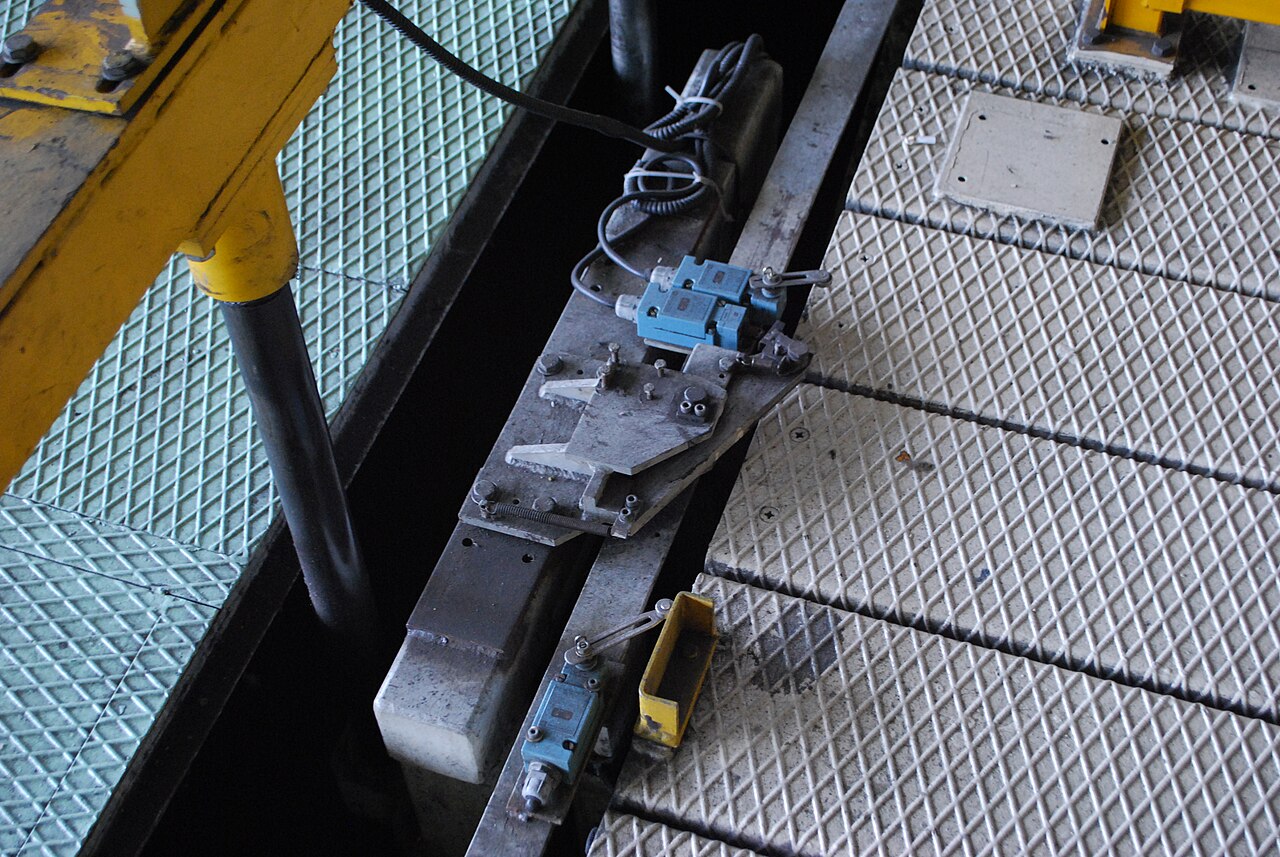
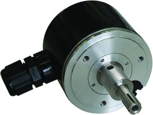
And on the front panel: 2 potentiometers, an analog value from 0 to 255.
7 · Inputs, outputs, actions
Open or closed at rest?
NO · normally open
| Button state | The PLC reads |
|---|---|
| at rest | 0 |
| pressed | 1 |
NC · normally closed
| Button state | The PLC reads |
|---|---|
| at rest | 1 |
| pressed or wire broken | 0 |
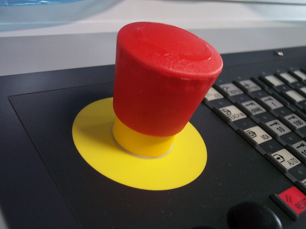
STOP and emergency stop: always NC. A broken wire acts like a press: the machine stops.
7 · Inputs, outputs, actions
Outputs: what the PLC drives
Lamp, relay, buzzer
Digital: on or off
DC motor
PWM: pulse width sets the speed
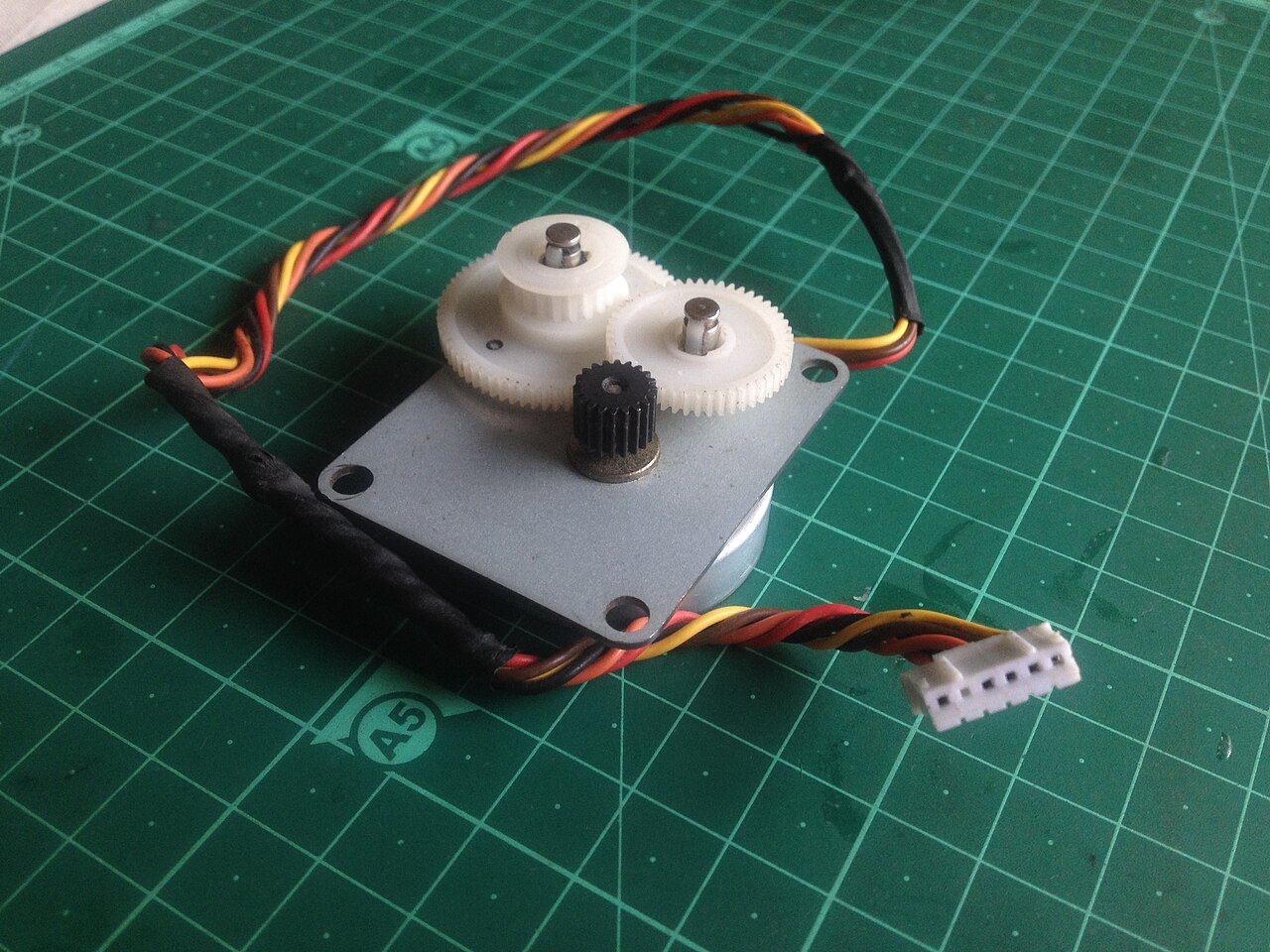
Stepper motor
PTO: one pulse = one step
7 · Inputs, outputs, actions
Three kinds of action in GRAFCET
Continuous
1
PUMP
X1
PUMP
at 1 while the step is active
Stored
3
MOTOR := 1
X3
X7
MOTOR
stays at 1 until “MOTOR := 0” (step 7)
Delayed
1
LAMP (3 s/X1)
X1
LAMP
starts 3 s after the step becomes active
8 · The lab
The method, in every lab
Specification
read it, ask questions
I/O table
addresses and symbols
GRAFCET
the wanted behaviour
Program
commented ladder
Tests
and fault injection
Preparation: before the session
as a group, on paper or on the virtual trainer
At the bench: during the session
the instructor signs each step
8 · The lab · the golden rule
A fault must stop the machine. Never start it.
Every lab ends with fault tests: broken wire, missing sensor, stop during motion.
8 · The lab
How each lab is marked, out of 20
3
Preparation
6
Program
6
Bench demonstration
5
Report
I/O table and GRAFCET correct before the session
Functions shown, symbols and comments, every fault leads to a safe state
One report per group
8 · The report
Six parts, one form
1 · Preparation
calculations and prior answers
2 · Analysis
I/O table, symbols, GRAFCET
3 · Program
commented listing, network by network
4 · Tests
expected, observed, signature
5 · Faults
does every fault lead to a safe state?
6 · Discussion
answers to the questions, signed declaration
The report form is handed out with the lab sheet: just fill it in.
Next session
Lab 0: a first program
Connect the PC to the CPU
Start / stop with self-holding
Break a wire: does the machine stop?
To prepare: the I/O table. To practise: the virtual trainer on the course website.
Photo credits
| Photo (Wikimedia Commons) | Author | Licence |
|---|---|---|
| Bottling line | Olivier Lemoine (Photo-Terroir.fr) | CC BY-SA 4.0 |
| Siemens PLC S7-200 CPU | Projuktiponno | CC BY-SA 4.0 |
| Relay room (Panel Decoder) | Panel Switchman | Public domain |
| Micro, mini and rack PLCs | Bisgaard | CC BY-SA 3.0 |
| Siemens SIMATIC S5 PG 730 | Palatinatian | CC BY 3.0 |
| Inductive proximity sensor | IP83 | CC BY-SA 3.0 |
| Limit switches | Mixabest | CC BY-SA 3.0 |
| Emergency stop (Not-Aus) | Stahlkocher | CC BY-SA 3.0 |
| Rotary encoder | Joao Paulo Chagas | CC BY 4.0 |
| Geared stepper motor | Kushagra Keshari | CC BY-SA 4.0 |
Diagrams, GRAFCETs, ladder networks and timing charts: made for this course.